PlotterStudio
Draw, turn images into paths and prepare the job for a pen plotter, from CAD to G-code.
What you get
From drawing to plotter job
Prepare drawings for pen plotters in the same environment where you edit them: CAD, job origin, pen plan, preview, export and G-code sending. It helps cut down manual steps between editor, converter and control program; behaviour on the machine depends on the profile and the controller.
CAD for preparing drawings to scale
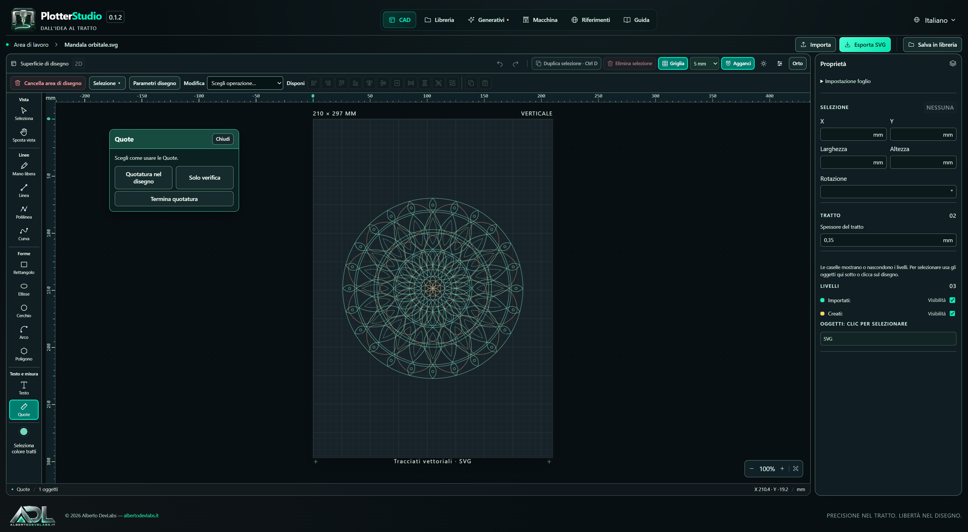
Draw in millimetres with lines, curves, polylines, shapes, numeric input, rulers, grid, snaps and orthogonal constraint. A4, A3, square and custom formats help fit the job to the sheet; position, dimensions and rotation are adjusted from the properties.
Importing and job storage
Open SVG and DXF files, split the independent parts and edit position, colour and geometry. DXF is converted to SVG. Save editable objects to the local library or export an SVG copy; re-importing does not necessarily rebuild the original editable structure.
Screenshots and video
Features
Path editing and layout
Parallel and cross hatching, offset, fillet, smoothing, joining, simplification and nodes let you prepare the toolpaths. Mirroring, copies, alignments, distribution and groups organise the compositions. Previews come before confirmation; some operations work on polyline geometries.
Machine control and G-code console
Control controllers over USB/COM or TCP G-code with adapters for GRBL 1.1, grblHAL, FluidNC, Marlin, Smoothieware and RepRapFirmware. Jogging, homing, coordinates, console and run commands are included. Software support does not certify every board, version or proprietary protocol.
Setup wizard and calibration
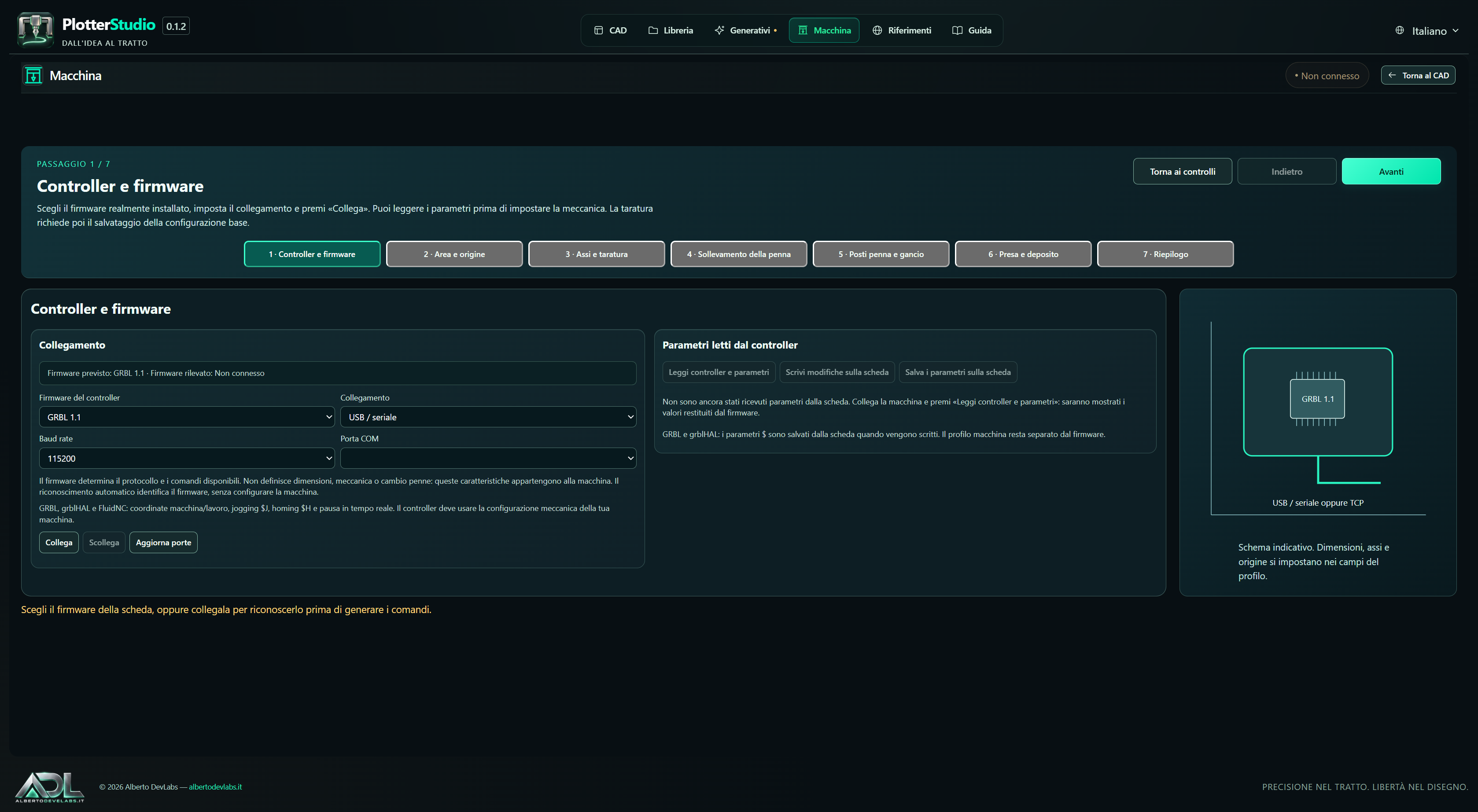
A seven-step procedure collects controller, work area, axes, pen, tool slots and sequences. Calibration uses requested and measured distance, with steps/mm calculation for belt and pulley. Profiles are saved and exchanged as JSON; saving on the PC does not automatically write to the board.
One or more pens in the same job
Associate colours and line widths with T numbers and choose single pen, manual swap or automatic change via macro or pick-up/drop-off sequences. Custom profiles handle 1–255 slots; the four-pen GH-01 template is included. Mechanics, actuators and commands must be configured for the actual hardware.
Positioning, preview and simulation
Choose CAD origin, user origin or current position with nine-point alignment. The preview distinguishes rapids from drawn strokes, plays back the path and estimates duration. Frame highlights or traces the bounding box on custom profiles. Controller simulation covers the three GRBL families, without physically checking the tools.
Photographs turned into strokes
Turn JPEG and PNG images into paths with 40 Plotterfun Extended algorithms and twelve Photo to strokes styles. Compare previews, adjust the parameters and use monochrome or RGB/CMYK separations, then insert the result into the CAD or export it. Automatic previews can be disabled and interrupted.
Generative drawings and custom scripts
Create compositions with GenerativeArt, Plottter, Plotter Hacks, Voronoi, Maze, Plot Writer, Harmonograph and the original generators. vsketch adds 25 examples and Python scripts with parameters in the interface. The result can be used in the CAD; personal scripts run in the generator process.
Lettering and dimensions in the drawing
Use Windows fonts or single-stroke Hershey/EMS fonts, lay out text straight or on an arc and measure distances and angles. Dimensions can be used just for checking or be added to the drawing. Permanent ones do not automatically follow the geometry and can be drawn by the plotter.
Vector maps and QR codes
Create posters from places or coordinates with roads, water, parks, railways, buildings and coastline, using OpenStreetMap with attribution and cache. It also generates QR codes based on size, pen tip and error correction. Maps require access to the online services; the readability of the physical QR depends on how it is produced.
Multilingual interface and support resources
Work in Italian, English, German, French or Albanian, with themes and a light/dark sheet. The library offers search, favourites, examples and previews; Help and References gather instructions and resources. Translations can be extended through external JSON files.
System Requirements
- 64-bit Windows; the provided installer requires Windows 10 or later.
- Microsoft Edge WebView2 Runtime.
- Complete package with runtime, scripts and resources: the executable alone does not include all the required components. Python is included.
- For actual machine control: a controller with supported firmware, a USB/COM port or a compatible TCP G-code endpoint, and a profile configured for the machine.
- Internet access to fetch map data and for the first download of the Quick Draw categories.
- Only for building from source: Rust toolchain for Windows and C/C++ build tools.
Documentation
PlotterStudio: purpose and version
PlotterStudio 0.1.2 is a Windows desktop application dedicated to preparing drawings for pen CNC plotters. It is meant for those who start from vector drawings, photographs or generative compositions and need to obtain dimensioned paths, assign them to pens and prepare or send the G-code.
CAD, library, generators and machine controls are gathered in the same environment. The practical benefit is being able to edit geometry, layout and colours before moving on to machine preparation, without transferring every stage between separate programs. The functions described here are present in the sources and in the project materials; they do not attest to testing on any particular machine.
Author: Alberto DevLabs, https://albertodevlabs.it. Stated distribution: Paid Only. The version in the sources is 0.1.2, under development. The materials distinguish these sources from the previous local installer 0.1.1: they do not attest to the availability of a new 0.1.2 installer.
Installation and requirements
Installing the Windows package
64-bit Windows and the Microsoft Edge WebView2 Runtime are required. The installer defined in the project requires Windows 10 or later and uses the Inno Setup .exe executable format.
Once you have the installation package, launch it and follow the procedure. The default folder is %LOCALAPPDATA%\Programs\PlotterStudio; installation is for the current user and the desktop shortcut is optional. Then start PlotterStudio from the shortcut or from PlotterStudio.exe in the installed folder.
The complete package must include the runtime, resources, scripts and components required by the generators. Copying only the executable is not the same as distributing the complete program. The Python runtime is embedded: a separate Python installation is not required for the complete package.
A connected plotter is not necessary for drawing and local generation. To move a machine you need a supported controller, a USB/COM serial connection or TCP G-code, and a profile that correctly describes axes, work area and pen commands. Fetching maps requires Internet access; vsketch Quick Draw requires it on the first download of the category.
No quantitative minimum requirements for memory, processor or free space are documented that could be presented as guaranteed.
Building from source
Anyone building must also have the Rust toolchain for Windows and the C/C++ build tools. From the project root:
cargo build --release
.\target\release\PlotterStudio.exe
build.rs prepares the runtime and resources next to the executable; these elements must accompany it in the distribution. The commands are instructions for using the sources, not operations carried out during this editorial preparation.
Workflow
- Open the CAD and set the sheet format and orientation.
- Draw, open an SVG/DXF file or generate paths from a photograph, an algorithm, a map or a QR code.
- Adjust geometry, position, colours and sizes; use SVG splitting to work on individual parts.
- Save to the library to keep the editable objects; export SVG when an external copy is needed.
- Open Machine, choose or configure the profile and set pens, origin and job parameters.
- Examine the preview and prepare the G-code. Export it or connect the controller and use the run commands.
Interface, languages and storage
Pages and display
The main pages are CAD, Library, Generative, Machine, References and Help. Ordinary switching between CAD and Machine happens in the same window and preserves drawing and connection. Machine configuration is separate from the operating controls.
In the CAD the left bar gathers view, lines, shapes, text and measurements. At the top there are history, erase, grid, snaps, Drawing parameters, Edit and Arrange. On the right, sheet and object properties are available. Contextual panels can be moved by their header.
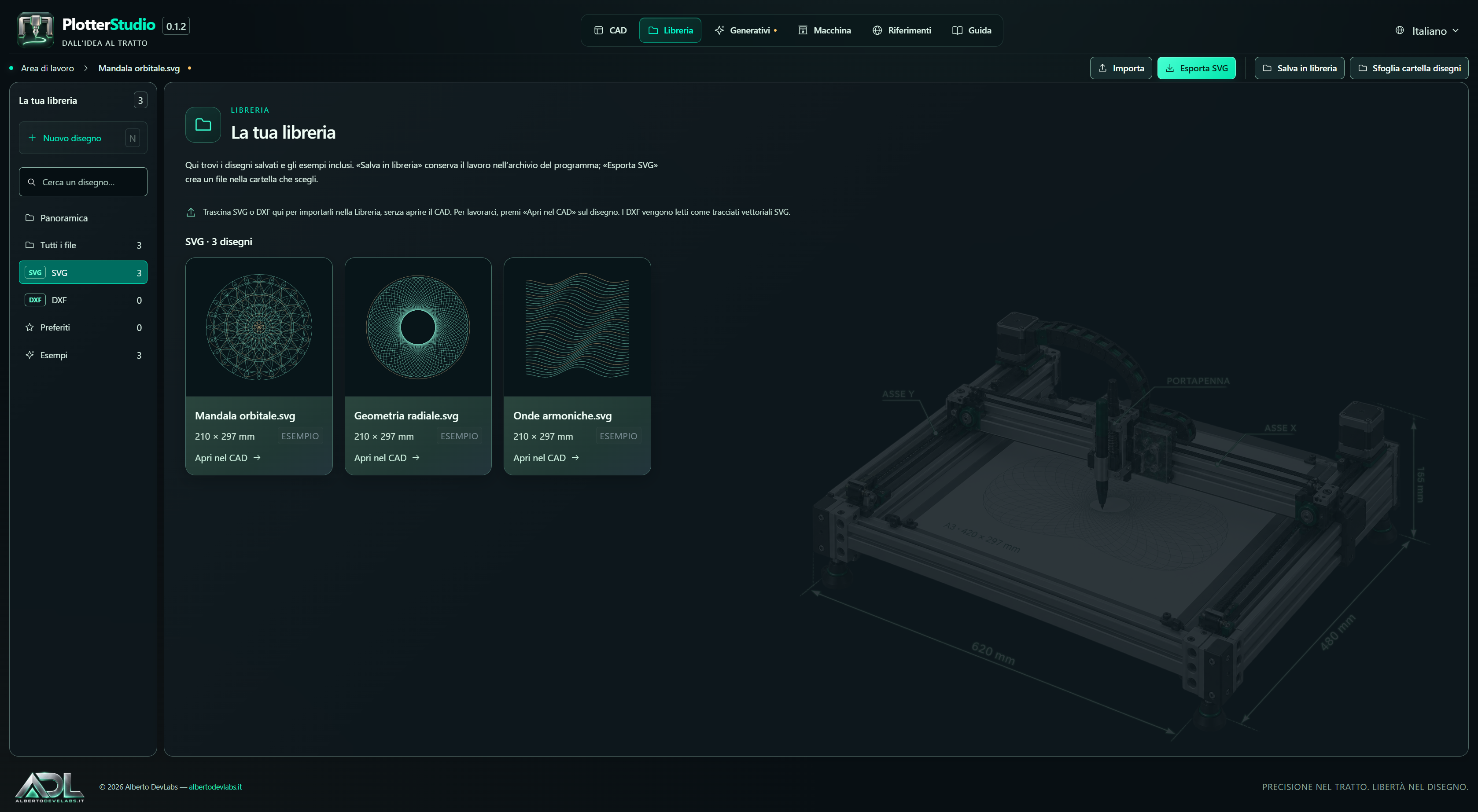
The Petrol, Chalkboard and Ink themes are available, along with light or dark sheet display. The window adapts to the monitor and the DPI factor. The illustrative plotter view in the Library does not replace the machine profile measurements.
Languages
Italian, English, German, French and Albanian are included. JSON files in the languages folder next to the executable can add languages or replace the built-in translations. Missing keys fall back to the Italian text.
Local data
Storage is under %LOCALAPPDATA%\PlotterStudio: studio.json, Disegni\SVG and Disegni\Originali. The library is local. The map cache uses the map-cache subfolder; Quick Draw keeps the downloaded data in its own local cache.
Importing, library and outputs
Opening and storing a drawing
Press Import to open the internal browser: it offers folders, a path field, Desktop, Documents and an SVG/DXF filter.
- Open in CAD requires a single selected file and opens it without storing it immediately.
- Import into the library lets you store several files, to be opened later from the gallery.
- Dragging SVG/DXF files into the window adds them to the library.
DXF is read and converted into SVG paths, keeping the DXF category. Importing can adopt the file dimensions as a custom sheet; the format can be changed in the properties. JPEG and PNG go into the photo generators: they must become paths before being used as a plotter drawing.
The library offers SVG and DXF categories with counters, search by name, all files, favourites, examples and removal. Three initial examples are present; the project materials also report ten JPEG/SVG pairs in resources/drawings.
Clicking the thumbnail opens a large preview. Open in CAD is a separate action. The preview closes from the button, with Esc or by clicking outside the panel. The light/dark background adapts to the drawing colours.
Saving and exporting
Save to library keeps the document and the information of its editable objects, including text and dimensions. Export SVG saves a vector copy in the folder chosen through the internal browser and asks for confirmation before overwriting.
An SVG that is exported and later re-imported does not guarantee the rebuilding of the same structure of text, dimensions and editable parts kept in the internal storage. To continue a job, also keep the library version.
The main outputs are documents in the local library, SVG files, .gcode programs and .machine.json profiles. The machine profile contains program settings, not a firmware to be installed on the board.
CAD: sheet and tools
Sheet, coordinates and view
Coordinates and dimensions are in millimetres. A4 210 × 297 mm, A3 297 × 420 mm, square 200 × 200 mm and custom format are available. Portrait/Landscape swaps the dimensions; the command is also accessible from the sheet caption.
The rulers follow coordinates, zoom and view panning. Grid shows or hides the lines; Grid step adjusts their spacing. Snaps can use grid, endpoints, centres, midpoints and other available geometric points. Ortho constrains drawing to horizontal/vertical; Shift provides the constraint while drawing.
Zoom +/− and the wheel only change the display. 100% restores the base factor; Fit view shows the sheet; the hand pans the view without moving the objects. Changing format modifies the document, changing zoom does not.
Drawing with the mouse
| Tool | Use |
|---|---|
| Freehand | Press and drag to trace |
| Line | Drag from the start point to the end point |
| Polyline | Click the vertices of a segmented path |
| Curve | Click the points of a smoothed path |
| Rectangle and ellipse | Drag to define width and height |
| Circle | Indicate the centre and a point on the circumference |
| Arc | Indicate centre, start point and end point |
| Polygon | Choose from 3 to 128 sides, then centre and vertex |
| Text | Set the content and click on the sheet |
| Dimensions | Choose check only or insertion in the drawing |
Polylines and curves can be open or closed. Complete polyline/curve, Enter or a double click confirm. Esc cancels the path being prepared and ends the tool: it is not the same as completing it.
Numeric input
Drawing parameters creates new shapes through Insert shape; it does not automatically apply the values to the selected object.
- Polygon: centre X/Y, radius, sides and rotation.
- Arc: centre X/Y, radius, start and end angle.
- Circle: centre X/Y and radius.
- Rounded rectangle: X/Y, width, height and radius.
- Polyline and curve: list of X,Y pairs, one per line, and open/closed choice.
For example, 10,10, 50,10 and 50,40 on three lines describe three points in millimetres. Inserted objects are then edited through the properties and the CAD commands.
Selection, properties and organisation
Selection and basic transformations
A click selects an object or its group; Shift + click adds or removes elements. Selection is also possible from the Objects list. A window from left to right includes the objects entirely contained; from right to left it also includes those crossed. Ctrl A selects the visible objects.
Dragging an element that is already selected moves the selection; several elements move together. The dashed outline of the selected contours belongs only to the view and not to the exported SVG.
The properties include X/Y, width, height, rotation, colour and line width from 0.05 to 20 mm. For a line, width and height represent the extension along the axes: assigning a height to a horizontal line tilts it. To measure its real length use Distance between points. Dimensions have dedicated properties and do not resize like ordinary shapes.
The Imported and Created checkboxes control layer visibility, not selection.
Arrange, groups and clipboard
Arrange offers left/right/top/bottom alignment, horizontal or vertical centring, centring on the sheet and horizontal or vertical distribution. A single object aligns to the sheet; several objects align to the selection. Centre on sheet always uses the sheet. A group is treated as a block; distribution requires at least two distinct objects or groups.
Group links the elements so they can be selected and moved together, without merging the paths. Copy and Paste use the CAD internal clipboard. Duplicate selection, also with Ctrl D, creates slightly offset copies.
Splitting an SVG
An imported SVG is initially a single object. Split group / SVG breaks up a group or divides the independent elements of the file. In paths without fill it can also split independent subpaths, preserving curve data, position, transforms and colours.
Filled subpaths that define holes stay together so as not to alter the appearance. An element with no independent parts cannot be divided further with that command. After splitting, select the desired part to move it, delete it or change its colour.
The previous limit of 2,000 elements for splitting has been removed; operations that multiply copies keep separate limits.
Colours and line width
The colour picker sets new strokes and modifies the current selection. Assign colour in the right-click menu offers a palette and the choice of another colour. To change only some parts of an SVG, split it first.
Colour and line width define the pen plan groups; changing colour does not directly perform a tool change. The visual line width does not change the diameter of the tip fitted on the plotter.
Text and dimensions
Straight text and text on an arc
Text supports multiple lines, available Windows fonts, single-stroke Hershey/EMS, regular, bold, italic and bold italic. Size in millimetres, rotation, straight or arc layout, radius and curvature direction can be changed in the properties. A radius that is too small is flagged.
To create text choose the tool and click on the sheet; to edit it, select it. The properties update the text while editing. Characters become outlines or SVG paths; the library keeps the text data for later editing.
Check measurements and permanent dimensions
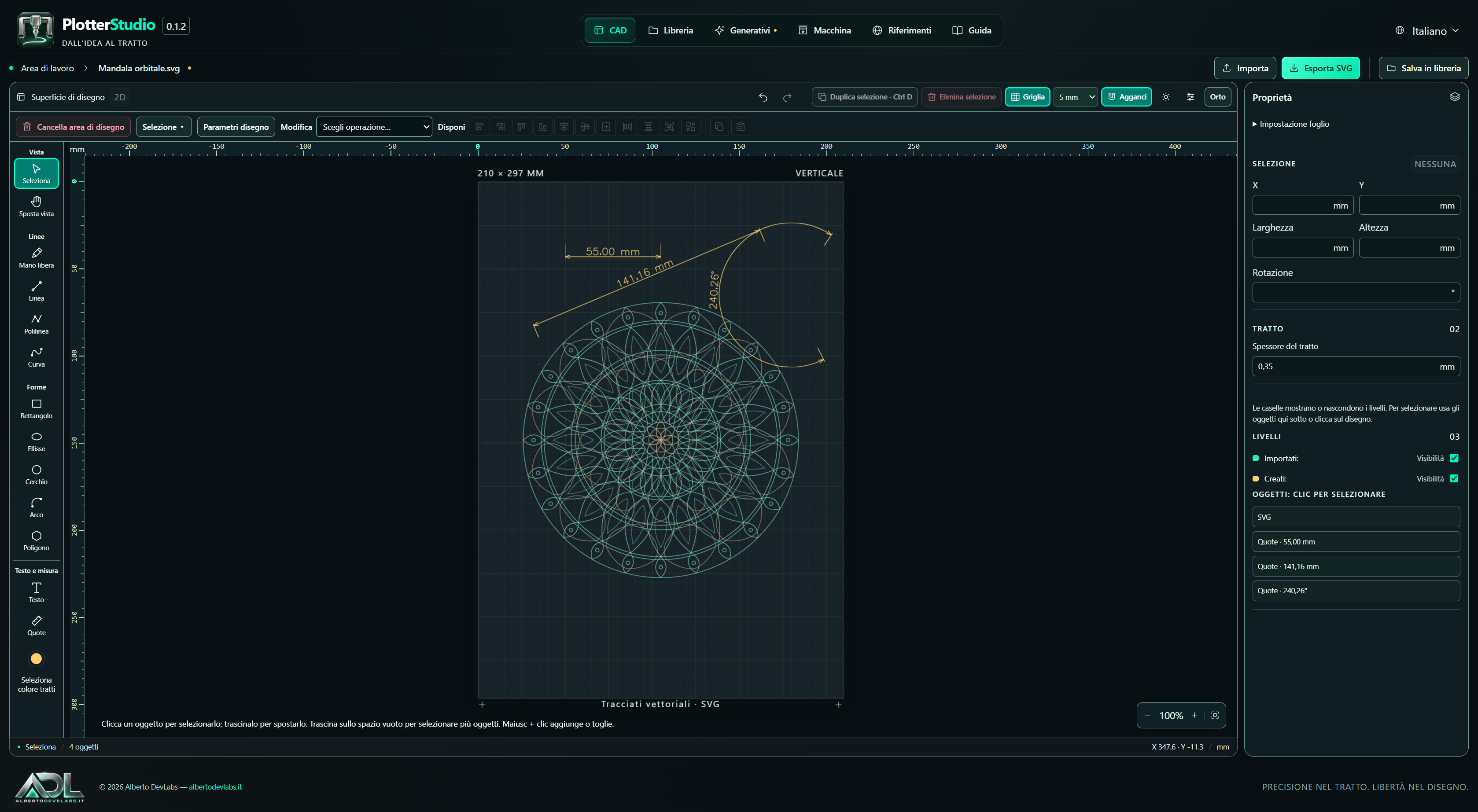
Check only shows the measurement without creating an object. Dimensioning in the drawing inserts line, arrows and text.
| Type | Result |
|---|---|
| Distance between points | Real distance, including slanted |
| Horizontal | X difference |
| Vertical | Y difference |
| Chained | Real distance between each consecutive pair |
| Arc angle | Angle in degrees, not arc length |
You can adjust offset, text height, decimals, clockwise/counter-clockwise direction of the arc and text orientation: along the dimension, horizontal, vertical or at a custom angle. The text can stay horizontal even on a vertical dimension. For the arc, a positive offset moves the line outwards, a negative one inwards; for straight dimensions it changes the side.
The tool stays active after a measurement. End dimensioning or Esc finishes it; in chained mode the last point becomes the first of the next measurement. To edit a selected dimension use Edit dimension from the properties or from the right-click menu.
Permanent dimensions are independent objects and do not update automatically if the measured geometry changes. They go into the SVG and can be drawn by the plotter. Use Check only when the measurements must not be part of the job.
Path editing
Select the objects, choose the operation, set the parameters, look at the dashed preview and confirm. Merely choosing the operation does not modify the document.
| Operation | Parameters and behaviour |
|---|---|
| Parallel hatching | Closed contour, spacing and angle; keeps the border |
| Cross hatching | Two perpendicular families of lines |
| Offset | Creates a parallel contour while keeping the original |
| Round corners | Fillet radius; replaces the selected strokes |
| Smooth the strokes | Smoothing tolerance |
| Join nearby paths | Tolerance between endpoints of compatible open paths |
| Reduce the drawing points | Simplification tolerance |
| Edit the drawing points | Draggable nodes of a single object |
| Split independent paths | Divides the selectable SVG parts |
| Flip left/right or top/bottom | Mirrors about the centre of the selection |
| Copies in rows and columns | Number of rows/columns and X/Y steps |
| Copies around a centre | Centre X/Y and total number over a full turn, including the original |
| Move the selected objects | X/Y displacement, including negative |
The offset uses a positive distance and a side choice: Outside/Inside for closed contours, Side 1/Side 2 for open paths. Create offset or Enter confirms.
Geometric operations may use a polyline representation. Fillet, smoothing, joining and simplification require compatible colours; unsuitable selections or parameters are flagged. The dedicated SVG splitting, on the other hand, preserves the original curves.
To edit nodes, select an object, choose Edit the drawing points and confirm; drag the nodes and finish with the dedicated command or Esc. Undo recovers the changes already applied. Objects with too many nodes require simplification: it is not an editor for the original Bézier control points.
Erasing, history and shortcuts
The right-click menu offers select all, groups, splitting, colour, edit dimension where applicable, deletion, numeric or mouse movement and 90° rotation in both directions.
Delete selected, Del and Backspace remove the selection. Clear drawing area empties the job, including hidden layers, without deleting the drawings already stored. New drawing prepares a new document. Undo/Redo move through the history; replacing and closing a modified job use the application confirmations.
| Key | Action |
|---|---|
| V / P / L | Selection / freehand / line |
| R / E / H / T | Rectangle / ellipse / pan view / text |
| N | New drawing |
| Ctrl A | Select the visible objects |
| Ctrl D | Duplicate |
| Ctrl O | Import |
| Ctrl S | Save to library |
| Ctrl Z | Undo |
| Ctrl Y or Ctrl Shift Z | Redo |
| Del / Backspace | Delete selection |
| Shift + click | Adds to or removes from the selection |
| Enter / double click | Complete polyline or curve |
| Enter with offset active | Confirm offset |
| Esc | Ends or cancels the tool, or closes the context menu |
Drawing shortcuts are not intercepted while typing in fields or when a dialog is open.
Generative, photographs, QR and maps
Catalogue and outputs
In Generative choose family and algorithm, load the image if required and adjust size, colour, line width and parameters. Generate the preview; Insert into drawing transfers the result into the CAD, while exporting produces an SVG. Stop cancels the processing in progress.
| Family | Content |
|---|---|
| Plotterfun Extended | 40 photo algorithms with parameters, monochrome and RGB/CMYK separations |
| GenerativeArt | Built-in register of generative, geometric and fractal drawings |
| Plottter | Calligraphy, TurtleToy and Vectorize Trace generators and plug-ins |
| Plotter Hacks | Eight built-in tools with SVG capture |
| Voronoi | Cells, shapes and insets |
| Maze | Mazes, curves and solution |
| Plot Writer | Single-stroke writing |
| Harmonograph | Local harmonographs |
| vsketch | 25 examples and Python script editor |
| Original generators | Eight generators of the project |
The photo gallery can automatically start the previews of the 40 Plotterfun algorithms with two workers and a preview resolution of 384 px. Automatic start can be disabled and the processing can be interrupted. The final result keeps the quality and colour controls of the chosen algorithm: the preview is not a promise of quality or execution time.
Photo to strokes and QR
Photo to strokes offers twelve styles derived from the Calamo engine. Load the photograph and adjust contrast, brightness, inversion, auto levels and style-specific controls. The result is a set of paths, not the original raster photograph.
QR code generates geometries based on the content, the code size, the pen tip and the error correction level. The settings help prepare the drawing; they do not automatically attest to the readability of the QR produced with any pen and medium.
Maps
Search for a city or a place or enter coordinates; choose extent, size, title, layers and hatching. The layers include roads, water, parks, railways, buildings and coastline. The result is a vector poster that can be inserted into the CAD or exported.
The search uses Nominatim and the OpenStreetMap data are fetched through Overpass. Attribution and a 30-day local cache are provided. Fetching depends on the Internet, on service availability and on the data present in the chosen area.
vsketch scripts
The examples and the custom editor use a class derived from vsketch.SketchClass; the vsketch.Param entries expose the controls in the interface. The user script runs in the generator process; Stop terminates that process.
Quick Draw downloads the category at the first generation and keeps it locally. The other requirements depend on the example or script chosen; the included runtime avoids a separate Python installation for ordinary use of the complete package.
Machine configuration
Profile and firmware
The profile describes dimensions, sheet origin, axes, travels, speeds, accelerations, steps/mm, pen, offsets, tool slots and sequences. The firmware is the controller program that interprets the commands. Changing profile does not install firmware and does not automatically configure pins or wiring.
A new installation starts from a custom machine to be configured. The initial values must be customised. X/Y/Z and A/B/C are axes; T1 and following are pen slots.
Saved profiles are chosen in the controls or in the configuration. Creation, duplication, renaming, deletion with confirmation and .machine.json import/export are available. Creation and duplication remain unsaved until Save machine. Leaving the editor discards the unsaved new profile; the wizard, on the other hand, has its own draft resume function.
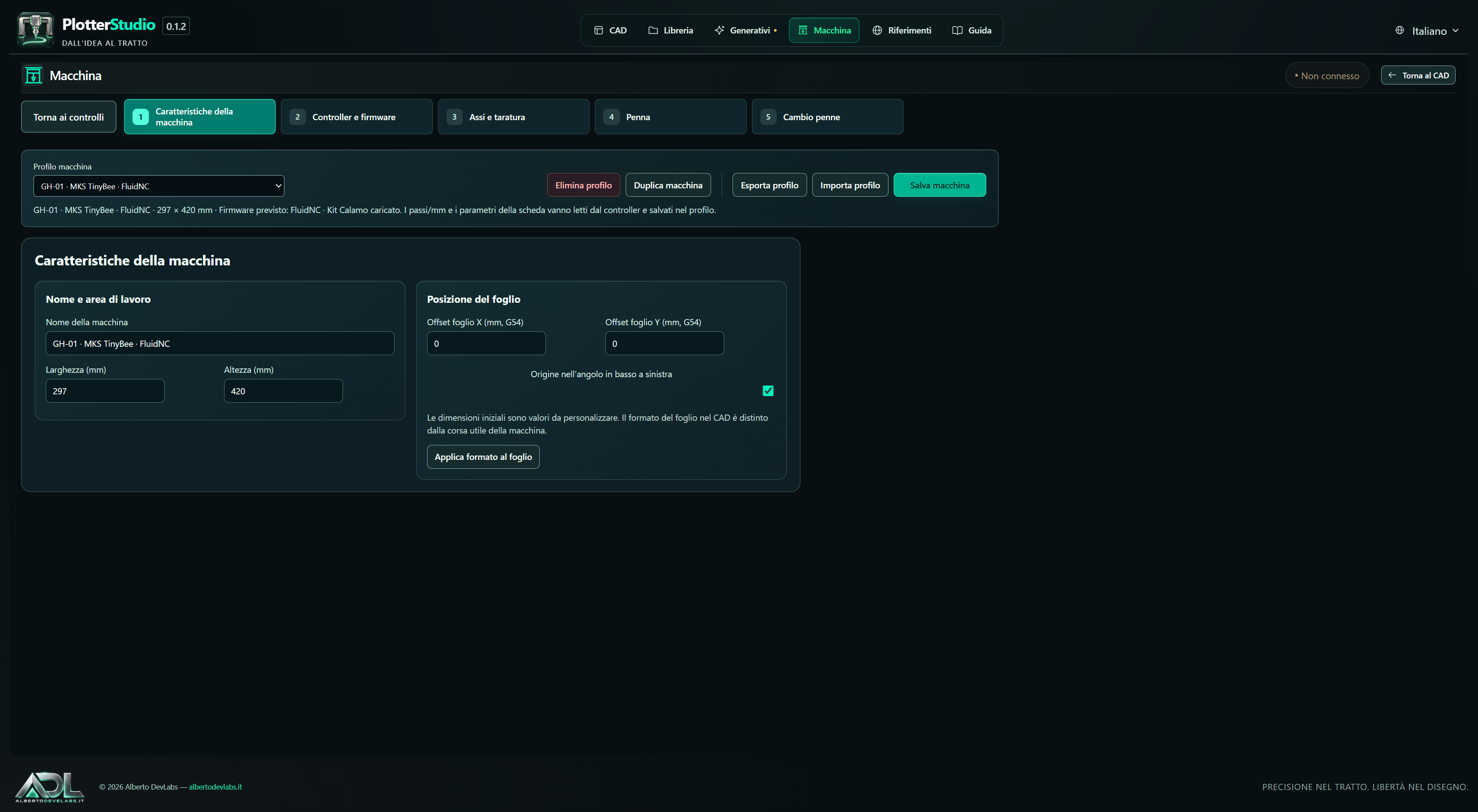
Applying the format to the CAD is distinct from saving the profile: it updates the sheet of the same drawing. The CAD format does not identify the controller, nor does it alone determine the machine work area.
New machine: seven steps
New machine opens the wizard in the same window. The numbered steps are clickable, with Next/Back and illustrated diagrams. Returning to the controls, you can use Resume configuration to continue the draft.
- Controller: choose the installed firmware and the USB/serial or TCP connection. You can connect and read the parameters before completing the mechanics; jogging requires the basic profile to be configured.
- Area: indicate the work area and the sheet position relative to the machine origin.
- Axes and calibration: configure limits, speeds and steps/mm; use movement correction, mechanical calculation and advanced parameters. Save profile and connect keeps the profile on the PC before connecting.
- Pen: choose axis, servo, PWM or custom commands; distinguish home, contact, lifted height and pause. Apply settings for testing keeps the values; movements start only from the dedicated buttons.
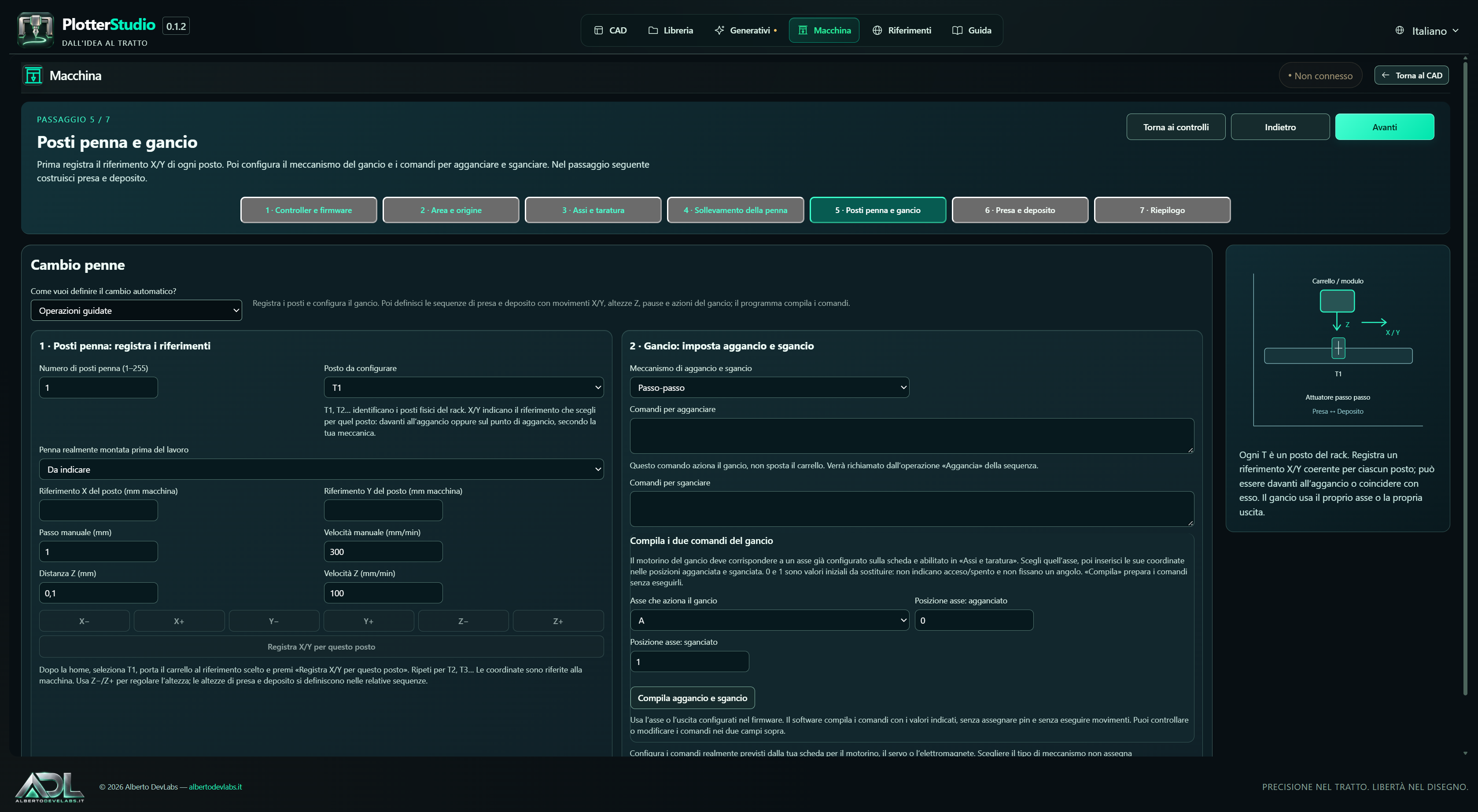
- Slots and hook: set T1…Tn, coordinates, mounted pen and actuator.
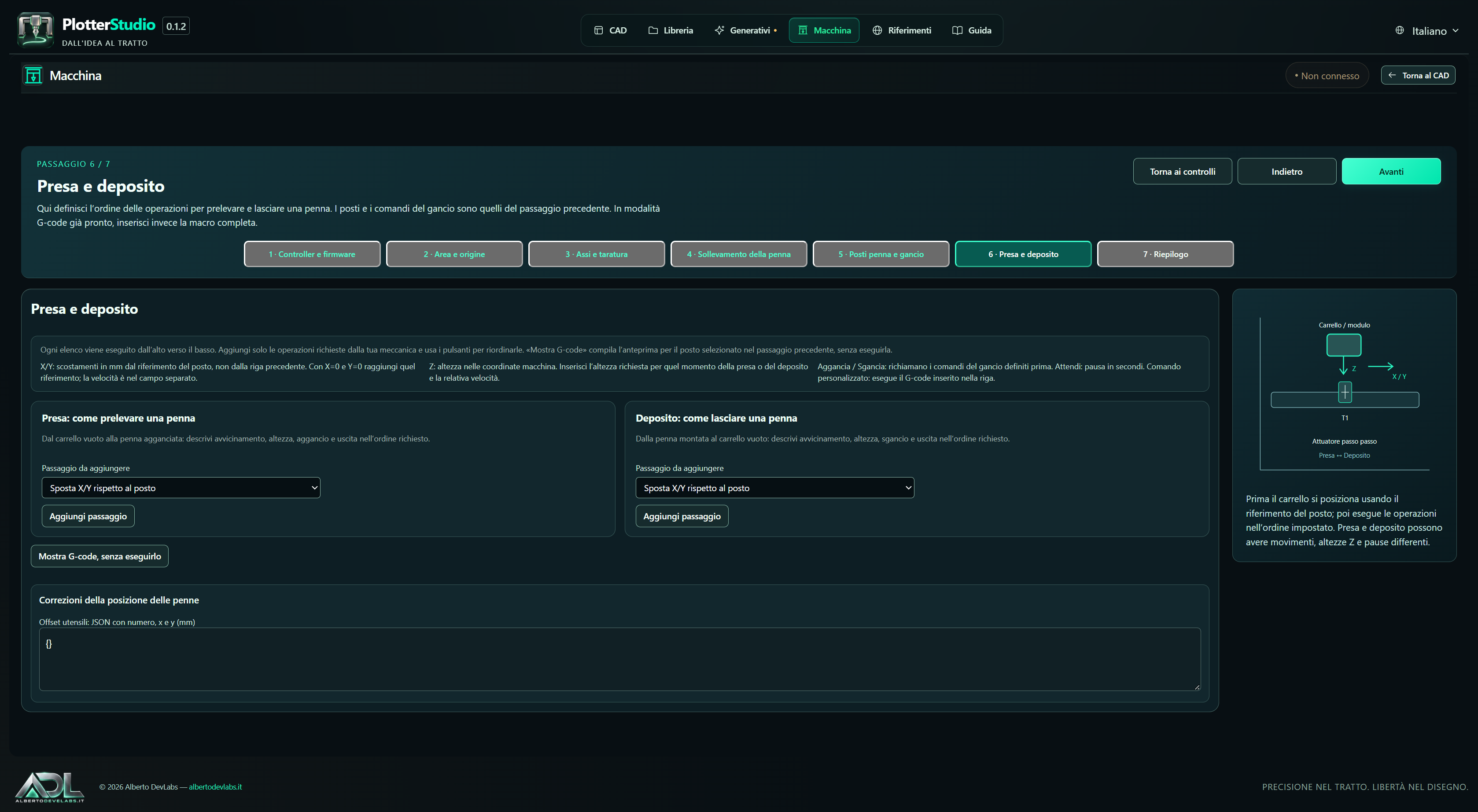
- Pick-up and drop-off: fill in two separate sequences or use the macro field.
- Summary: check the data and save.
The diagrams explain the relationships between parts of the machine: they do not provide the correct positions or sequences for unknown mechanics.
Editing a saved profile
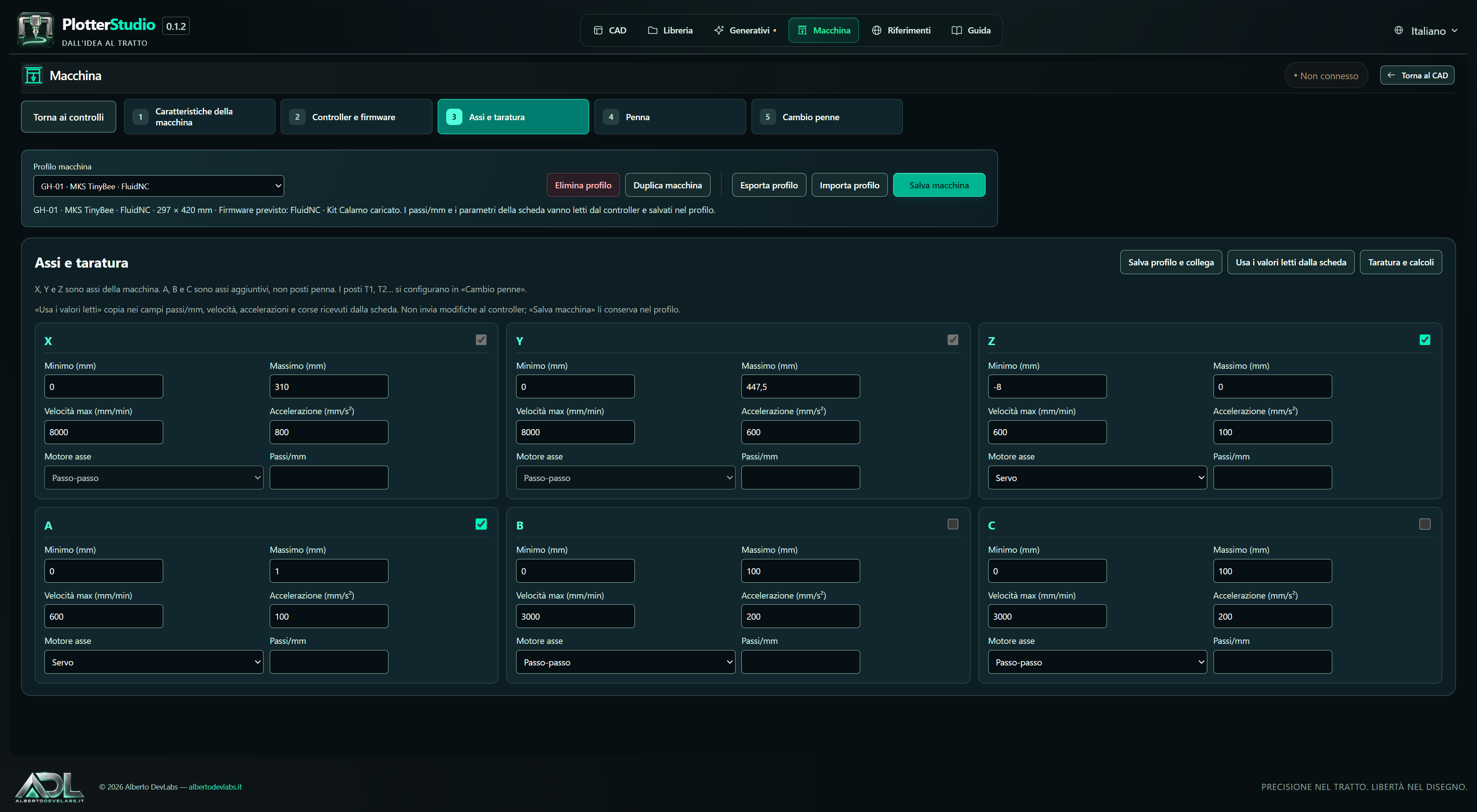
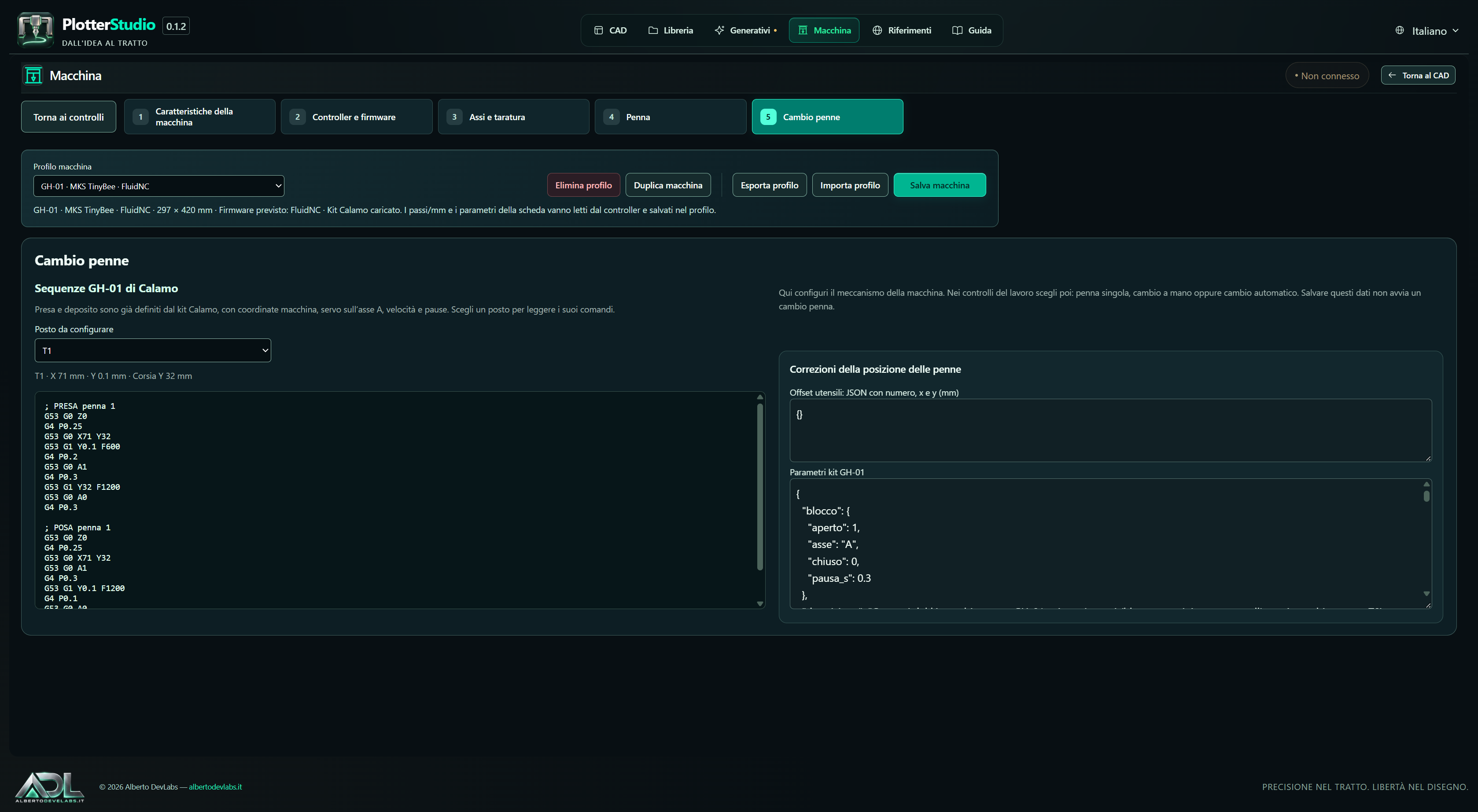
Edit machine profile opens five sections: characteristics, controller, axes, pen and pen change. It is not the Next/Back procedure. Save machine, Import profile and Export profile act on the profile; Back to controls exits the editor.
In Axes and calibration, Calibration and calculations opens movement correction, mechanical calculation and advanced parameters. Back to axes restores the grid without losing the values. Use the values read from the board copies the received parameters into the profile fields, without writing to the board.
Calibration
Choose the axis, set a positive or negative distance, request the movement and enter the distance actually measured. The correction is:
new steps/mm = current steps × requested distance / measured distance
You need to know the initial value; the program flags when it is missing. The belt-and-pulley calculator uses steps/revolution, microsteps, belt pitch and number of teeth.
Saving keeps the values in the profile. Writing to the board is a separate action, available depending on firmware, read parameters and machine state. Speed values are converted into the units used by the profile when copied from the native parameters.
Pen and lifting
Configure the pen motor and the way it is commanded: axis, supported servo, PWM or macro. Adjustment can use small axis movements, recording of contact and lifted height and calculation of the lift from the contact. Home and pauses are configurable.
A PWM S value does not automatically represent an angle. The servo command and its range depend on the firmware; the generator distinguishes Smoothieware syntax from the M280 P… S… used for Marlin/RepRapFirmware. Standard GRBL does not offer a universal servo command. Commands and configuration consistent with the actual board are required.
Firmware, connections and parameters
Available adapters
| Firmware | Identification and settings | Movements and status |
|---|---|---|
| GRBL 1.1 | $I, $$, $G; $number=value editor | $J, $H, ? status, coordinates and hold in real time |
| grblHAL | Separate detection within the GRBL family | GRBL transport; axes and macros depend on the board |
| FluidNC | Separate detection; YAML mechanical configuration | Jogging, status and G-code according to the board configuration |
| Marlin | M115, M503, M92, M203, M201 | G28, G91/G1/G90, M400/M114, M280 servo |
| Smoothieware | M115, M503, M92, M203, M203.1, M204 | G28, jogging, M400, work position M114 and machine position M114.4 |
| RepRapFirmware / Duet | M115, M92, M203 S0, M201 | G28, jogging, M400/M114, machine coordinates from the report and M280 servo |
Automatic detection uses queries without movement. The expected firmware and the detected one are shown separately; an unknown response or a mismatch does not enable movements.
USB/COM requires an available serial port. TCP requires an endpoint that accepts the expected G-code protocol: an HTTP port, a Telnet login or a proprietary API are not equivalent.
Writing and persistence
The editor distinguishes the read value from the new value. Writing is explicit, with the machine stopped, and is followed by a re-read. GRBL/grblHAL parameters are persistent when written. Marlin and Smoothieware have a separate M500 button. RepRapFirmware also requires saving in the configuration file; FluidNC uses YAML. These files are not modified automatically.
Marlin uses the firmware's logical reference without requiring G53/G54; the user origin is applied by the software. Manual console commands do not receive the G53/G54 reference conversion.
M203 expresses speed in mm/s on Marlin/Smoothieware and in mm/min on RepRapFirmware; copying to the axes converts to mm/min. The generated pauses use P in seconds for GRBL and milliseconds for the other adapters. Custom macros must follow the dialect of the selected firmware.
Pause and stop
On Marlin, Smoothieware and RepRapFirmware the stream pause waits, through M400, for the movements already accepted. Stop sends M112: the board must be reset and homed again before resuming. How immediate the response is also depends on how the firmware handles the emergency stop.
The implemented adapters do not certify every board or version. AxiDraw/EBB, HPGL and proprietary protocols require specific adapters not included in G-code support alone.
Pen plan and tool change
Job modes
The mode is chosen in the job controls, separately from the mechanism configuration.
- Single pen: performs no changes or swap pauses, even if the drawing contains several colours.
- Manual change: the job stops for the swap; after the change you use Resume.
- Automatic change: uses a custom macro or guided drop-off and pick-up operations.
Colour and line width form the pen plan associated with the T numbers. You must indicate the pen actually mounted at the start, or the empty carriage.
Slots and guided operations
Custom profiles allow 1–255 slots. After homing, select T1, move the carriage to the chosen reference and use Record X/Y for this slot; repeat for the others. The reference can be in front of the hook or on the hook itself, depending on the mechanics.
The Z−/Z+ controls use dedicated Z distance and speed. They do not record a single height for the slot: the pick-up and drop-off heights belong to the sequences.
Pick-up and drop-off are separate lists, executed from top to bottom. Each step can move X/Y relative to the slot reference, move Z to a machine height, wait, hook, unhook or send a custom command. X/Y are not relative to the previous line. Lines can be reordered or deleted.
Structured movements use the travels and speeds of the profile. Show G-code displays the result without performing movements. Guided change requires a valid homing.
Actuator and macros
Stepper, servo, solenoid or custom commands can be configured. Fill in hook and unhook generates the command text in the fields: it does not execute them and does not configure pins or wiring. M42 generation is available for the firmware provided by the interface; in other cases macros supported by the board are required.
For a stepper hook the values represent axis coordinates in the two positions. The initial values 0 and 1 must be customised: they are not a universal switch nor servo angles.
In ready-made G-code mode, the field contains the complete change; {tool} identifies the requested pen. There is no need to fill in the guided sequences as well. Macros must be compatible with the controller and the mechanics; standard GRBL does not implement M6.
At the end of the job the last mounted pen is kept. After a stop or an error during the job it must be indicated again.
GH-01 — Calamo — 4 pens template
The included template keeps the kit-specific data: area X 0–310 mm, Y 0–447.5 mm, A3 sheet 297 × 420 mm, origin 6.5 / 27.5, Z from −8 to 0, A axis for the hook, four slots X 71 / 137 / 203 / 269 with Y 0.1 and Y corridor 32. The kit's sequences, speeds, pauses and offsets are present; the recipes for T1–T4 can be consulted.
GH-01 profiles already saved are preserved. Steps/mm and pins cannot be derived from the template alone and must be completed for the actual board. The kit keeps its own positioning and does not use the custom Frame path.
Operating controls, origin and G-code
Moving and monitoring the machine
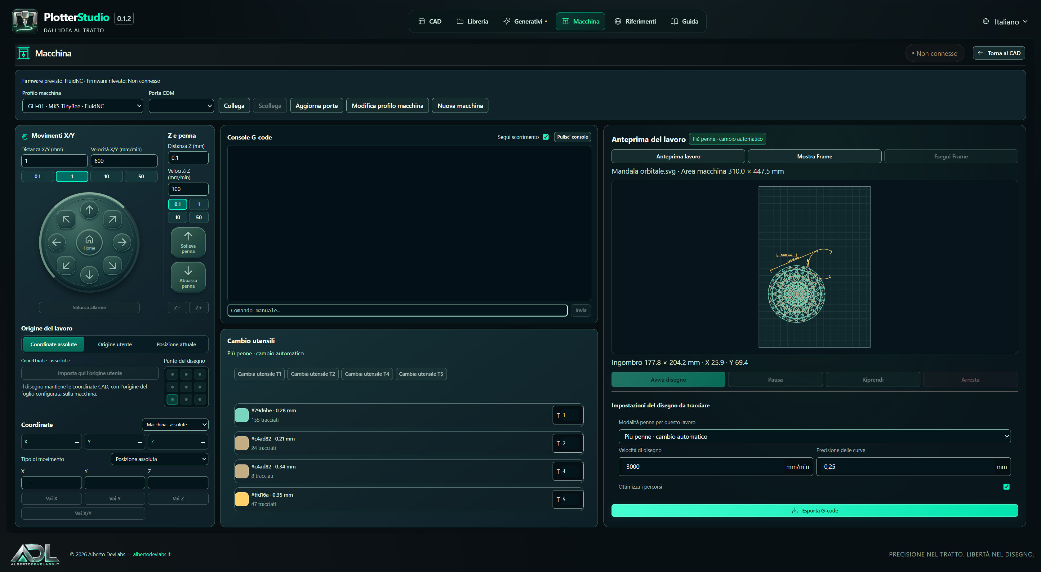
The operating screen offers profile selection, port and connection, X/Y movements including diagonals, adjustable distance and speed and quick steps of 0.1 / 1 / 10 / 50 mm. Z has its own distance and speed. Pen up/down uses the profile commands.
Homing, work zero, unlock, machine/work coordinates, absolute position and relative distance are available. The console shows the G-code sent and the responses, with manual command, auto-scroll and view clearing. Actions depend on the connection, the identification and the updated state of the controller.
Choosing the origin
The job can use the absolute CAD coordinates with the configured sheet origin, a stored user origin or the current position. For the last two modes, the nine points choose which point of the bounding box coincides with the origin.
Storing the user origin records the position in PlotterStudio without rewriting G54 on the board. Displaying machine or work coordinates is distinct from choosing a relative offset.
Show Frame highlights the bounding box on screen. Run Frame, on custom profiles, traces the rectangle with the pen lifted and returns to the initial X/Y position, using the configured origin and limits. It is a real movement, distinct from the preview. Preview, program and Frame share the origin choice.
Preparing, exporting and starting
Choose profile, pen mode, T associations, drawing speed, curve tolerance and job options. The program prepares the paths and any change sequences. Standard conversion is handled internally, without requiring the choice of the technical engines in the ordinary configuration.
The preview distinguishes rapids from drawn strokes. Planner, time playback and duration estimate use the profile's speeds and accelerations; they do not constitute a guaranteed measure of real time.
Export G-code produces a .gcode file. With the controller ready, Start sends the program; Pause, Resume and Stop manage its execution according to the firmware. Progress and responses are visible in the controls. Manual change requires user intervention before resuming.
Simulation and conversion limits
Connection simulation is available for GRBL, grblHAL and FluidNC, with virtual status, linear movements, planner, pause, stop and zeroing. It does not simulate Marlin, Smoothieware or RepRapFirmware and does not physically verify servos, magnets, friction or successful hooking.
Curves are converted into G1 segments with configurable tolerance. Export requires supported geometries: images, imported SVG texts not converted to paths and complex SVG features do not automatically become drawing commands. The converter can reject jobs that are too complex, invalid macros, incomplete profiles or geometries outside the expected limits.
Permanent dimensions are paths and can become part of the job; the graphic line width does not change the physical pen. To keep the project editable and structured, keep the document in the library in addition to the exports.
Documentation, licences and verification status
The Help page explains the CAD operations. References gathers resources, fonts, videos, firmware and sources. The project includes docs/CAD.md, docs/MACCHINA.md, CHANGELOG.md and THIRD-PARTY-NOTICES.md.
The embedded components keep the attributions and licences of their respective authors, including the MIT, AGPL-3.0, GPL-3.0 and PSF licences stated in the notices. Provenances are recorded in vendor/sources.json. The commercial distribution of PlotterStudio does not replace the licences of the individual components.
Technical references already indicated by the machine manual: GRBL, Marlin, Smoothieware, RepRapFirmware and FluidNC.
The previous materials report a successful local build and a start-up of version 0.1.2, without complete testing of the interface or the hardware. This write-up is based on targeted readings of the materials and the sources: no files were written and no tests, builds, USB/TCP trials, movements, servo or pen change tests were carried out. Implemented functions, simulation and compilation are not equivalent to tested hardware compatibility.
Get it PlotterStudio
Premium Version
Draw, turn images into paths and prepare the job for a pen plotter, from CAD to G-code.
Buy – €69License for 3 computers · How buying works